
DIY – UPDATE
IMPORTANT ! High voltage = danger to life
The reconstruction of these projects requires knowledge of electrical engineering, experience with high voltage, the ability to read and understand circuit diagrams, the use of measuring instruments, and knowledge of systematic troubleshooting in electrical circuits.
Using the Soken rotary switch as an impedance selector switch
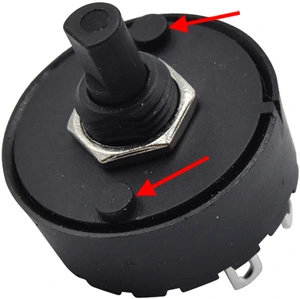
Unfortunately, the impedance selector switch that we have been using in our kits for years is no longer available. It is replaced by the Soken rotary switch, which can switch almost the same power and is a very good replacement for the old switch. However, it may not fit directly into the amp's chassis, and some adjustment is required:
Depending on your chassis and front panel, you may need to remove (with a knife) the two catches on the rotary switch housing so that the mounting nut can be screwed on.
The voltages in the circuit diagrams differ from my measured voltages. Where is the error?
Always make sure that you are using a good quality meter with charged BATTERIES and that the voltage ranges are set correctly (AC or DC).
Voltages can vary considerably. 10 - 20 % are possible depending on the time of day, because both the mains voltage itself and the tolerances of the individual components have an effect on the voltages. Also, the voltages without tubes are much higher than with tubes.
The reference voltages given in the circuit diagrams are for orientation only.
On the project pages of the LoW projects, the power supply is not explained. How do I have to build it?
For all LoW projects we use the PSU-Mini, which is perfect for this purpose. Please refer to the Datasheet of this power supply for building instructions and wiring examples.
Common Errors
Unfortunately, the same mistakes are made over and over again during assembly. To avoid this, you should follow the specifications in the schematic exactly. In particular, grounding is often neglected, although it is actually elementary. Here are the most common mistakes and their consequences
Wrong or missing grounding. This can cause hum, noise, or a non-functioning amplifier.
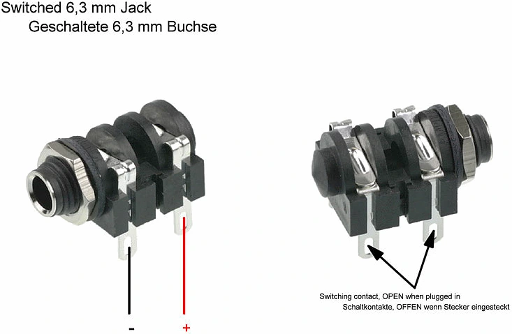
Wrong connection of the in or output jack. Most kits use switched jacks. This allows the input to be grounded when no jack is plugged in, thus "muting" the amp. However, this jack is often connected the wrong way around, so the input does not work. The output jack is also often connected incorrectly, which also causes the amp to not produce sound. Therefore, it is important to make sure that the jack is connected correctly. And this is how it works:
And the absolute top mistake you can make when something doesn't work: thinking the schematic is wrong or a component is defective - but this is very, very rarely the case.
If the setup does not work, the circuit must be checked step by step, if necessary several times, until the error is found. Unfortunately, we see time and time again that this is not done, and instead the fault is looked for in some component.
All our amplifier projects have been successfully rebuilt several times and the correctness of the plans has been confirmed. Errors in the schematics are corrected immediately and up-to-date schematics are posted online. The probability that a component has been delivered incorrectly is very low.
Outputransformers - Resistance and Impedance (EN)
We receive complaints from time to time, alleging that the transformer is defective because, for example, it exhibits 68 Ohms on the primary side instead of the required 6.6 kOhms. In such cases, the issue lies before the measuring device, and the transformer is, of course, not defective. The author of the complaint simply lacks an understanding of the difference between the ohmic resistance and impedance.
Ohmic resistance, also referred to as DC resistance, measures the resistance to electrical current flow in a direct current (DC) circuit, as described by Ohm's law: R = U / I. In the context of the transformer, the aforementioned measurement of 68 Ohms corresponds to the simple resistance of the copper winding. This value can be quickly and easily measured with a multimeter.
On the other hand, impedance is the complex resistance in an alternating current (AC) circuit and is composed of both the ohmic resistance and reactive components. These reactive components arise due to phase shifts between current and voltage, which are caused by inductive or capacitive elements in the circuit and the frequency (the coil or winding of a transformer is an inductor). In the example above, the 6.6 kOhms represent impedance. Measuring impedance requires considerably more effort compared to measuring DC resistance. Alternatively, specialized impedance measuring devices can be used.