Svetlana Amp
The Svetlana SV811/572 Amplifier
By: David Wolze
Abstract
This monobloc amplifier is designed to run any of the SV811 or SV572 series power triodes. Features include DC filament supply for the amplifier, fully regulated power supply, and power output of over 20 watts with a single output tube. As much as possible, the amplifier uses Svetlana tubes such as the 6AS7G and 6BM8 for the front end and regulator.
Amplifier Description
The output transformers are Hammond 1650R push-pull units, which are modified for single-ended operation by adding 0.030" air gaps. Nominal primary impedance is 5000 ohms, and the transformers are rated at 25 watts for single-ended operation. However, with the SV572 tubes operating at 700 volts and 150 mA, I have been able to push a good 40 watts through this iron.
The amplifier has a line stage, a front end, an output tube, a filament supply, a bias supply, and a regulated plate supply.
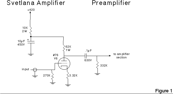
The line stage is operated outside of the amplifier feedback loop. See Figure 1 for illustration. It is required to increase the gain of the amplifier so that it can be operated from a CD player. The selection of the tube for this stage is critical; a medium mu triode such as the 6J5 or 6SN7 will work well here. However, for the ultimate sound, the older type 76 is the tube of choice. Since this amp is intended for high-end applications, I went with the 76. It is wired as an unbypassed voltage amplifier.
The front end utilizes the Svetlana 6BM8. The front end design is the secret to getting good efficiency from the power triode output tubes. Designers and builders should note that the SV811 and SV572 series output tubes are NOT receiving type audio tubes, they are based on TRANSMITTING tube design. Transmitting tubes are called power triodes because they require power on the control grid in order to provide optimum performance. Power may be provided to the output control grid by either an inter-stage transformer, or by a direct coupled cathode follower drive tube.
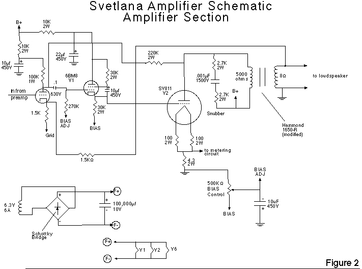
The triode section of the 6BM8 is configured as a high mu voltage amplifier. Again, the cathode resistor is unbypassed. See Figure 2 for illustration. The larger pentode section of the 6BM8 is wired as a true pentode cathode follower in order to handle the requirements of the power triode control grid.
The output tube is operated with direct bias, which is applied through the pentode cathode follower. A DC filament supply is provided in order to eliminate hum. A snubber consisting of a 0.001 µF 1600 volt capacitor and two 2700 ohm resistors in series (see Figure 2) improves the transient response of the output transformer.
Two feedback loops are provided in order to control the load on the power triode and to compensate for the differing characteristics of the various triodes in the SV811 and SV572 series. A local loop is applied from the output tube plate to the voltage amplifier plate. (see Figure 2). An overall loop goes from the output transformer secondary to the cathode of the voltage amplifier.
Power Supply Description
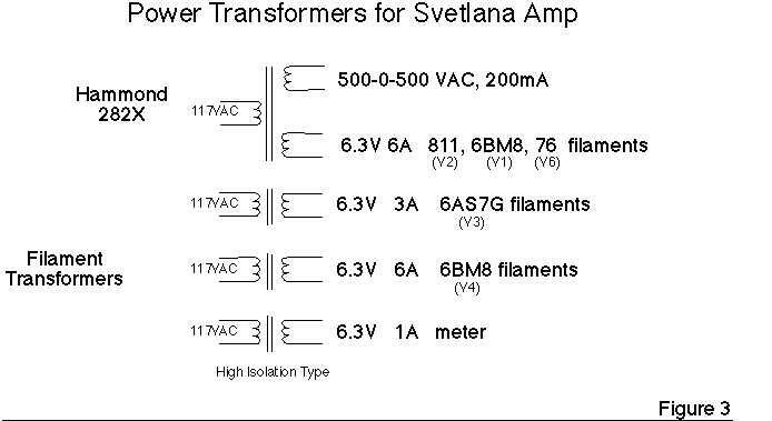
The power transformer for this amplifier is the Hammond 282X (382X outside the USA) unit. It has a 1000 volt centertapped secondary and a 6 amp filament winding. This transformer provides the plate supply, the filament supply, and the bias supply. Two additional filament transformers are required to handle the regulator heaters. See Figure 3 for illustration.
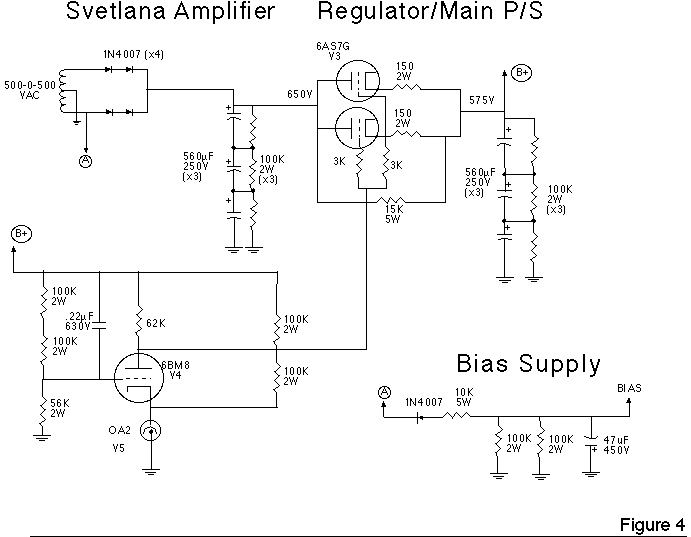
A solid-state rectifier and filter provide DC to the plate of the 6AS7G pass tube. A 15k 5W resistor is connected between the plate and cathode of the 6AS7G to prevent arc-over at power-up. See Figure 4.
The regulator is a simple 2-stage type that uses the 6BM8 triode section and a 0A2 regulator to feed the control grid of the 6AS7G pass tube. (See Figure 4) This regulator is set up to provide approximately 575 volts to the output tube plates. Voltage on the front end is reduced to about 420 volts by means of resistors.
DC filament power is provided for all of the amplifier tubes. The regulator tubes use AC filament power. See Figure 2. A Schottky bridge and a 100,000 uF 'thumper' capacitor (used to enhance car audio equipment) are used to rectify and filter the filaments.
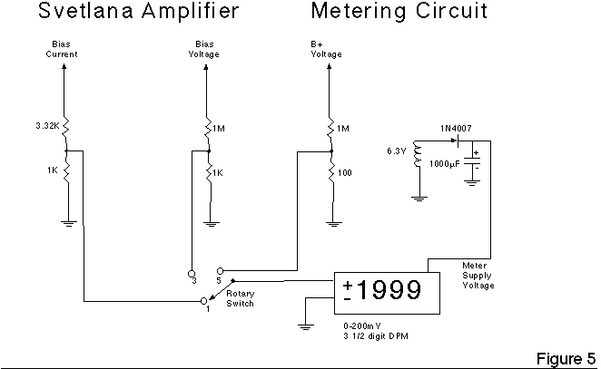
A metering circuit is provided on this amplifier to aid the user in adjusting the bias. See Figure 5. A selector switch allows cathode current, bias voltage, and plate voltage to be monitored on the digital panel meter. The meters that I used required high isolation 'Signal' type transformers; which are wound with the secondaries alongside and separated from the primaries.
Bench Testing the Amplifier
The amplifier was brought up on the bench using my trusty Heath IG-18 signal generator and Tek scope. Optimum performance was obtained with about 110 mA of cathode current. I happened to have a rare mu of 30 triode running; its bias was at about +10 volts. The mu of 30 triode gets more power than the lower mu types; I use them to test the amplifier and output transformer. They don't sound too bad, either!!!
Anyway, I got a clean 25 watts out; maybe 27 or 28 watts at clipping. Power bandwidth went from about 40 Hz to 15 kHz; small signal (5 watts) BW went from about 20 Hz to 30 kHz. Square waves had about 5% overshoot, but the snubber quickly damped the ringing.
Listening Tests
These amplifiers have made the rounds at Bay Area Tube Club member's homes and have been auditioned at the Vacuum Tube Valley magazine offices, as well. I happened to have a box of various mu SV811 and SV572 series tubes available for the panels' listening pleasure. Overall, listeners were very favorably impressed with the accuracy and detailed sound of these amplifiers. There was a 50/50 split as to whether the mu of 3 or the mu of 10 sounded better. The mu of 30 tubes had a harder, 'pentode' type of sound that the panels were not as impressed with. My favorite is the mu of 10; it provides a good solid sound rather between that of the triodes and pentodes. When the heavy metal goes on, though, I pull the '10s out and rock with the '30s!!
The information provided in this application note is intended for general design guidance only. The user assumes all responsibility for correct and safe usage of this information.