
TT MidiCntrl (Hardware)

The TT MidiCntrl is a modified version of the MIDI Switcher with the focus on the use as “foot controller”, which is needed e.g., for the control of the TT Midi Switcher.
The known buffer from the TT Midi Switcher is omitted and also the extra power supply, since these are not needed here. What has been added is a MIDI-Out, which is needed for sending MIDI-commands.
The connections E1 to E8 are defined as inputs and the connections A1 to A8 are defined as outputs, which are followed by a ULN2803A. The ULN2803A can handle larger loads (up to 500 mA per channel, if the power supply can supply the needed current) without additional driver circuits or flyback diodes for relays.
In order to make the MidiCntrl as universal as possible, there is also a connection for an I2C bus and an ISP interface, which makes it possible to program the MidiCntrl for your own purposes.
The heart of the MidiCntrl beats in an Atmega16 microcontroller, in which the software runs which controls the processing of the input and output signals. For own projects which build on the MidiCntrl hardware also an Atmega16 should be used, though basically also an Atmege8 can be used (DIL28 format).
The MidiCntrl works with a voltage of 5V internally. The supply voltage gets applied to the pins AC/+ and AC/- and should ideally be between 8 and 9 V. If a DC voltage is used, the pin AC/+ must be used for the positive pole and AC/- for the negative pole.
If it is necessary to operate the MidiCntrl with other operating voltages, usually only the voltage regulator must be adapted, e.g., 7803 instead of 7805. The used Atmea16 operates within operating voltages from 1,8 to 5,5 V (according to data sheet).
Circuit
One of the advantages of microcontrollers is they do not need a large number of external components while still are able to solve complex tasks. The same applies to the MidiCntrl, the external circuitry is quite clear and most of the components are only needed for the power supply and the MIDI-IN.
The resistors R90 and R91 are not included, since they are only needed when working with the I2C bus. For reasons of space, the ISP connection was realized with a 10-pin header instead of a larger socket. When using the ISP connector for on-board programming of the microcontroller, it is important to ensure the correct alignment of the connector cable.
Connections
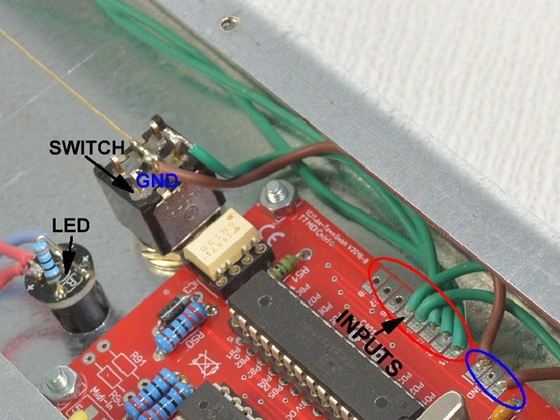
The layout of the inputs and outputs has already been shown above and can also be found in the circuit diagram. It should be noted that momentary switches must be used for the inputs, which must be located between the corresponding input and GND. The outputs get always switched to ground, with a polarized component, such as an LED, the positive side must be connected to the PWR connection and the negative connection must be connected to the required output. The operating voltage of the circuit is 5 V, depending on the used components it may be necessary to use dropping resistors.
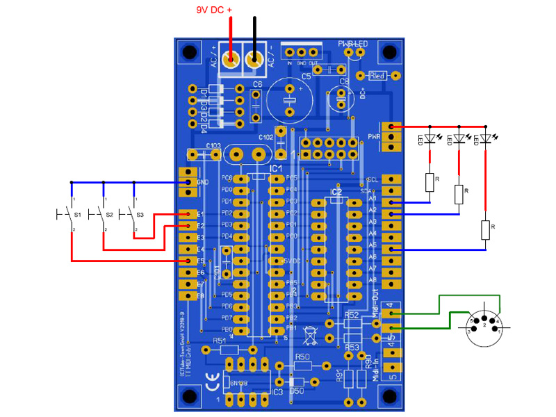
Example
The figure below (right) shows an exemplary assignment of inputs and outputs.
Other components
In order to build a complete foot switch based on the MidiCntrl more components are needed, of course. Especially for this application, we have different components in our delivery program which are geared to each other. Here is a short overview:
TT-Chassis Typ 051 – Floorboard – 5 Switch
Alpha Footswitch DPDT momentary, ON-(ON)
Result
… and here is an example of a completed floorboard.
