PoS
Tube amps don't really sound like tubes until they are opened up wide; unfortunately, this can result in a deafeningly loud volume. In order to reduce the output to a reasonable level, the energy generated must be dissipated; which is normally achieved through a series of resistors.
L-PAD
Very simple but very effective is the use of so called l-pads. Fortunately one can find already lots of information about l-pads in the wilderness of the web, so I will not go into details. Just follow the links:
TT PoS50
The PoS50 was the first attenuator which was published on this side. Since the release-date, the PoS50 was build many hundred times by DIY all around the world.
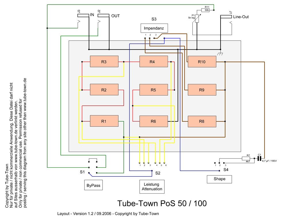
The schematic and layout diagrams below are for a simple and economical solution for an attenuator. The attenuator can dissipate up to 50 watts without additional cooling when the attenuator is assembled in a metal chassis.
A series of individual power resistors is used rather than a high-power potentiometer to keep the costs down. S2 switches these resistors in various combinations to set the amount of attenuation. Impedance matching is accomplished by the resistors R8, R9, and R10, which also do the real work and, of course, get quite warm. S3 sets the desired impedance. The circuit is quite simple and self-explanatory. S1 is a hard-bypass switch which removes the entire attenuator from the signal path, in which case the power at the output is equal to that at the input. Be aware that caution is required when switching at a high attenuation and volume levels.
Of particular interest is the tone stack, which is activated with switch S4. The purpose of this tone stack is to compensate for a possible high frequency loss through the resistance network. The high frequencies bypass the resistance network and are inserted in the output signal. A simple line out is also included, although it is not necessary for attenuation. The line-out signal can be sent to other amplifiers, or even into an additional input of the same amp, if it has multiple inputs.
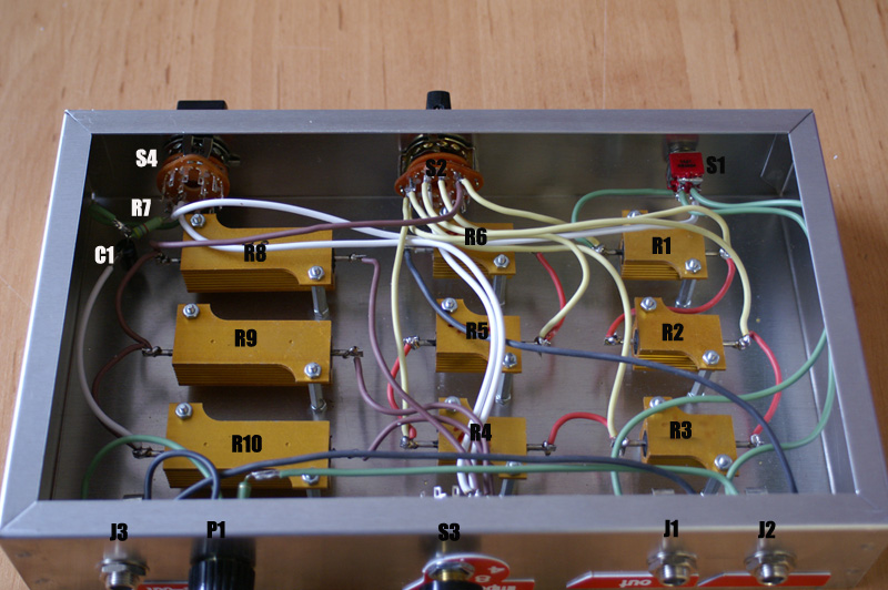
Silicon wire is used for the hookup. The power resistors themselves are mounted on standoffs. They could just as well be mounted directly to the chassis, but the standoffs improve ventilation.
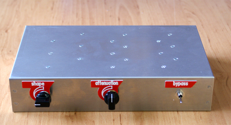
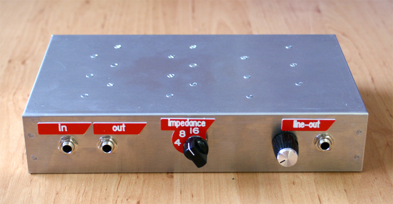
This is just one example of how the attenuator could be laid out. The circuit is not sensitive to interference and can be easily laid out as suits your purpose and available space.
The photos below show one possible layout. In this case, the attenuator is built in an aluminum Hammond 1444–16 chassis. This chassis is big enough, and there is enough room to easily position and fasten the components.
Material-List
| R1-R6, R8-R10 | kit-pos50-r |
| R7 | rmo-4k7-2 |
| R11 | rmo-47k-2 |
| P1 | apo16-10log |
| J1,J2,J3 | cl1160 |
| C1 | crt-4.7-100 |
| S1 | xsw35 |
| S2 | xsw19 |
| S3,S4 | xsw18 |
| Chassis | ha1444-16 |
| Cables | sil05-s |
| Cables | sil05-b |
| Screws M3 or M4 |
Pictures and plans

Pos100
The PoS100 attenuator is the steady further development of the PoS50 and provides a simple construction and simple handling together with a high power rating. The Pos100 can be used with a load of 4, 8 or 16 ohms and has a maximum power rating of 100 W.
Another addition is the available Line-Out, which can be used to directly process the output signal.
The old PoS100 and 200 Pro are obsolete
You can get the PoS100 kit in the TT-Shop
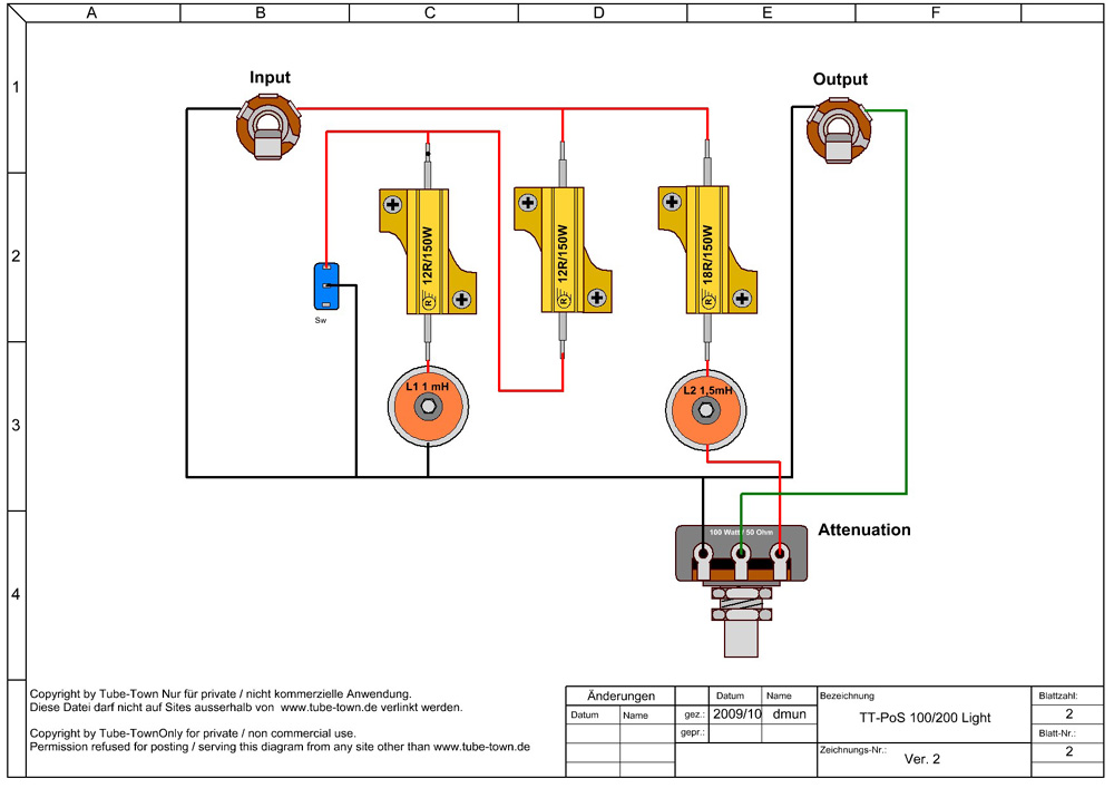
History
For historical reasons, here the “old” version of the Pos100/200 Light, obsolete.